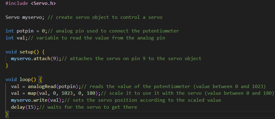

Select a component from the list to view its specific details.

View key specifications , about and short settings.

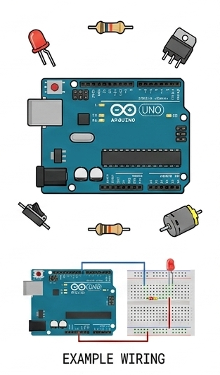
Understand how to properly wire components to the board.
Determine circuit requirements and operating specs.
Access quick calculators tailored to each component.
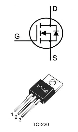
Max. VDS:
Max. ID:
Logic-Level compatible:
100V
4A (w/heatsink)
NO
Connection Example (Arduino Control)
PIN 9 -> Resistor -> GATE
DRAIN -> Load(+) -> Power(+)
SOURCE -> Load(-) -> Power(-)/GND
Voltage(V)
Current (I)
Resistance (Ω)
Enter two values , calculate the third.
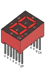
Common Type:
Segment Voltage (VF):
Current per Segment (If) :
Digit Height:
Common Anode
2.0V (Red LED)
20mA (max)
0.56 INCHES
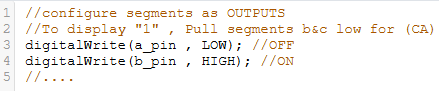
Pinout and Wiring Example:
PIN 1 (CA) -> 5V (Arduino)
PIN 2 -> Resisitor -> DP (pin)
PIN 3 -> Resisitor -> g (pin)
PIN 4 -> Resisitor -> f (pin)
PIN 5 (CA) -> 5V (Arduino)
PIN 6 -> Resisitor -> e (pin) -> Arduino PIN 5
PIN 7 -> Resisitor -> d (pin) -> Arduino PIN 6
PIN 8 -> Resisitor -> c (pin) -> Arduino PIN 7
PIN 9 -> Resisitor -> b (pin) -> Arduino PIN 8
PIN 10 -> Resistor -> a (pin) -> Arduino PIN 9
(228Ω resistor recommended per segment).
Voltage(V)
Current (I)
Resistance (Ω)
Enter two values , calculate the third.
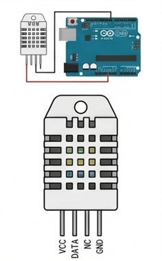
HUMIDITY RANGE:
TEMPRETURE RANGE:
OPERATING VOTAGE:
SIGNAL TYPE:
SENSING PERIOD:
0-100%RH (±2% RH accuracy)
-40 to +80 (±0.5°C accuracy)
3V TO 5V DC
Digital Signal via Signal-Bus
Average: 2 seconds
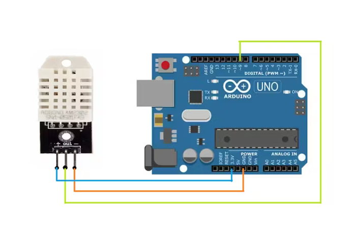
1. VCC(3V-5V Power Input) ->Arduino 5V
2. DATA (Signal-Bus I/O) -> Arduino Digital Pin
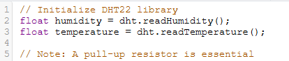
(e.g., Pin 2) (Requires 4.7KΩ Pull-Up resistor to VCC)
3. NC (Not Connected)
4. GND (Ground Connection) -> Arduino GND
Voltage(V)
Current (I)
Resistance (Ω)
Enter two values , calculate the third.
Working Voltage
Static Current
Sening Angle:
Detection Distance:
High Precision:
Input Trigger:
Echo Signal:
5V DC
<2mA
<15 degrees
2cm - 488cm
up to 3mm
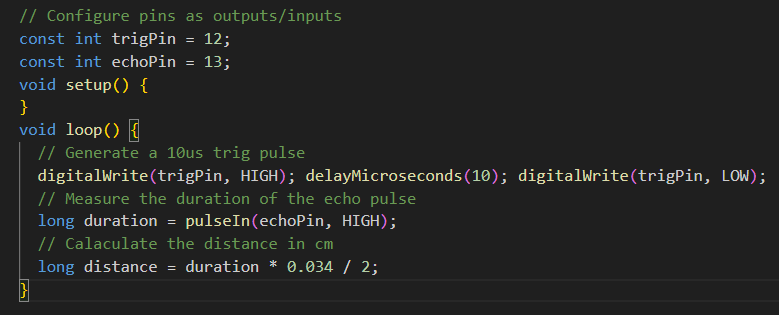
10μs TTL pulse
Output TTL PWL Signal
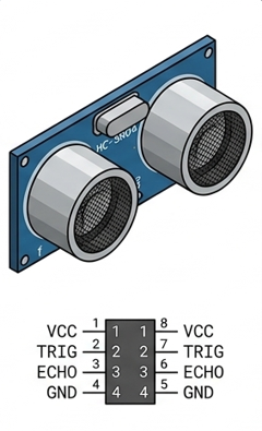
VCC (Pin 1): -> 5V(Arduino)
TRIG (Pin 2): -> Arduino PIN 12
ECHO (Pin 3): -> Arduino PIN 13
GND ( Pin 4): -> GND (Arduino)
Distance = (Time_High * Speed of Sound)/2
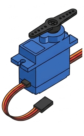
Working Voltage:
Operating Speed(4.8V):
Operating Speed(6.0V):
Stall Torque(4.8V):
Stall Torque(6.0V):
Dead Band Width:
Max. Angle:
Control System:
4.8V to 6.0V
0.12 sec / 60 degrees
0.10 sec / 60 degrees
1.8 Kg-cm
2.2 Kg-cm
1μs to 5μs
180 degrees
Analog Pulse Width Modulation (PMW)
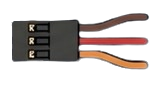
Brown(GND) -> -> Ground (Arduino)
Red(VCC) -> -> 5V (Arduino)
Orange(PMW Signal)-> -> PMW pin (e.g.,Arduino Pin 9)